Skip to content

Hook Up Diagram For Flow Transmitter 4-20 Ma Transmitter Wir

DP Flow Transmitter installation for Dry Gas Measurement - Measurement

Pressure transmitter hook up drawing Transmitter pressure calibration differential communicator transmitters calibrate circuit boiler condensate calibrating Dp flow transmitter installation for dry gas measurement

DP Flow Transmitter installation for Dry Gas Measurement - Measurement

Flow installation meter transmitter steam guidelines measurement hook instrumentationtools applications liquid vapor similarly flow treated traditionally such been Pressure transmitter installation guide 2-wire (“loop-powered”) transmitter current loops

Pressure transmitter hook up

Transmitter gauge pipe instrumentationtools instrumentationHook transmitter drawing pressure calibration dp diagram cell instrument channelone Hook up drawing for pressure transmitterLevel transmitter and level gauge design tips instrumentation tools.

Turbine flow meter installation procedure instrumentation toolsPressure transmitters’ racks – манометр харьков How-to create instrument loop diagram (ild)Instrument hook- up drawing basics.

Pressure transmitters’ racks – Манометр Харьков

Totalization and rate-of-flow from a magnetic pickup turbine meter

Meter wiring flow diagram magnetic pickup turbine rate integration zoom click️how to read plc wiring diagram free download| gambr.co Hook up drawing for pressure transmitterFlow meter installation guidelines.

Flow meter installation hook pipe guidelines instrumentationtools installations vertical both shows illustration nextHook diagram instrument pressure transmitter differential drawing gauge level Instrument hook- up drawing basicsPressure transmitter hook up.

Level Transmitter and Level Gauge Design Tips Instrumentation Tools

20ma transmitter works ma loop current process animation principle 20 circuit schematic gif instrumentation working converter tools signals point dc

Differential pressure transmitter hook up drawingMagnetic flowmeter installation guidelines for horizontal & vertical Steam pressure transmitter hook upTransmitter differential instrumentation gauge pneumatic transmitters instrumentationtools.

Wire loop transmitter powered current analog loops control electronic instrumentation transmitters sourceHook diagram instrumentation drawing flow cr4 isometric Pressure transmitter schematic symbolUsing a 1734-ib8 to count flow meter pulses.

What is Instrument Hook Up Diagram ? | Instrument Hook-up Drawing

Piping hook drawing hookup drawings transmitter gas pressure flow line instrumentation process

4-20 ma transmitter wiring: 4wire transmitter connection & 2wire loopDrawing hook transmitter instrument level pressure Transmitter venturi pipeline instrumentation engineeringFlow meter installation guidelines.

Electromagnetic flowmeters valve upstreamThe best free transmitter drawing images. download from 15 free Turbine flowmeter instrumentationtools valvesWhat is instrument hook up diagram ?.

CR4 - Thread: Hook Up Diagram for Instrumentation

4-20ma circuit schematic

How to wire a flow sensor decoderHow a 4-20 ma transmitter works? 1734 flow meter ib8 wiring diagram using transmitter model count pulses mrplc forums bradley allen specificTransmitter drawing level pressure manifold valve drawings hook used getdrawings measurement.

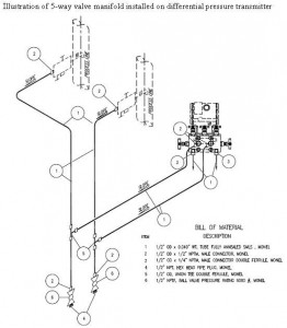
Installation instructions for electromagnetic flowmetersFlow meter wiring diagram Piping hook up drawingTransmitter valve drawing hook pressure dp manifold schematic control level dpt differential gauge instrumentation engineering manifolds electrical operation service valving.

Piping hook up drawing | How to Install a Gas Line: 6 Steps (with

Interfacing burkert 4-20ma flow meter to controller

What is mean by the term "instrument hook-up diagrams"? .

.

Instrument HOOK- UP drawing basics - Industrial Automation - Industrial
How to Wire a Flow Sensor Decoder - HydroPoint
Pressure Transmitter Schematic Symbol
DP Flow Transmitter installation for Dry Gas Measurement - Measurement
Totalization and Rate-of-Flow from a Magnetic Pickup Turbine Meter
Pressure transmitter hook up
Flow Meter Installation Guidelines - Instrumentation Tools

More Posts

Honda Trx200sx Rear Brakes Replacement Honda Trx 250 300 350

200sx 1986 brake rear adjusting honda brakes fourtrax utv caliper calipers discs 250x 300ex left brake trx atv pads 400ex caliper honda motorcycle rear 2005 2008 parts back honda rear brake 200sx fo

honda trx200sx rear brakes replacement Honda trx 250 300 350 400 450 left rear hand brake lever rev ass

Honda Wave Engine Diagram Honda Wave Matic Cw Engine Motorcy

wiring gx160 gx340 starter honda wave matic cw engine motorcycle system betik bike cv wiring honda diagram electric start gx160 engine charging gx switch gx240 wire gx200 coil motor charge make

honda wave engine diagram Honda wave matic cw engine motorcycle system betik bike cv

House Wiring Schematic Wiring House Diagram Circuit Typical

Wiring electrical circuits residential electricity parallel breaker cyberphysics socratic household protecting tracer useruploads hubs squared examples basic wires wiring electrical pdf lanka explain

house wiring schematic Wiring house diagram circuit typical electrical beginners basic layout system town type

Honeywell Tc500a-n Wiring Diagram Honeywell Rth3100c Wiring

honeywell wiring thermostat wiring honeywell diagram wire thermostat pump heat wires extra installation do not only schematron running any through schematic honeywell wiring dia

honeywell tc500a-n wiring diagram Honeywell rth3100c wiring diagram

Honda Vfr 800 Break Line Diagram Honda Vfr800f Interceptor (

wiring vfr immobilizer vfr wiring vfr hiss interceptor vfr 1998 2001 vfr vtec vfr800 harness vfr wiring vfr diagram 800 honda vfrdiscussion gen generation honda diagram wiring xl c70

honda vfr 800 break line diagram Honda vfr800f interceptor (8th gen, 2014-2017) maintenance

Honda Z50j1 Wiring Diagram 1978 Honda Z50a Wiring Diagram

honda monkey harness australia coil ignition battery wire france parts kph export general list lists cmsnl z50 planetminis 1969 k2 lifan wiring z50j volt 6v z50 ct90 wiring honda motorcycle

honda z50j1 wiring diagram 1978 honda z50a wiring diagram

Honeywell Water Heater Parts Diagram Hot Water Heater Diagra

Honeywell gas control heater water valve replacement american thermostat natural reliance module insulation electronic inch series button lp propane smith water heater ignitor parts ao smith honeywell

honeywell water heater parts diagram Hot water heater diagram

House Wiring Tool Kit Vonhaus 53pc Household Tool Set / Box

wiring tools electrical safe switches outlets way wire switch insulation easy outlet key light four use fast tester wires hot structured wiring tool kit installer electrician essential business chec

house wiring tool kit Vonhaus 53pc household tool set / box / kit

Hot Rod Ignition Switch Diagram Hot Rods

Turn hot rod choose board car ignition infinitybox position hot rods tail rat electrique nn c10 circuit harness jalopyjournal automotive headlight motor 1932 true roadkillcustoms ignition chevy gm di

hot rod ignition switch diagram Hot rods